
Vacuum Brazing with Advanced Front Loading
Vacuum Brazing with Advanced Front Loading
Unique Features and Benefits
- Compact Design - Internal gas blower and heat exchanger design reduces installation area and consumption of inert gas, reducing operating costs.
- Cylindrical Hot Zone - The cylindrical hot zone enables processing of oversized loads allowing for increased revenue.
- Circular arrangements of heating elements improve spatial temperature uniformity therefore minimizing distortion and eliminating the need for further machining.
- Wide Curved Graphite Heating Elements - The larger heating surface provides better temperature uniformity in the load. Significantly lower surface loading enables a higher heat transfer rate without over-heating of sharp edges of the load. This feature shortens cycle times and increases furnace productivity.
- Orbital Cooling System - Orbital gas cooling system provides for uniform gas distribution during the cooling cycle. This is particularly important in multi-layer and large loads and provides for better flexibility to suit the needs of heat treaters.
- Easy Maintenance and Full Support Package - The modular design allows quick easy exchange and repair of items within the hot zone. Diagnostic telecommunication modem and local service support is available at all times to every customer. These features reduce dramatically maintenance costs and increase furnace profitability.
Vacuum Brazing Furnaces Details
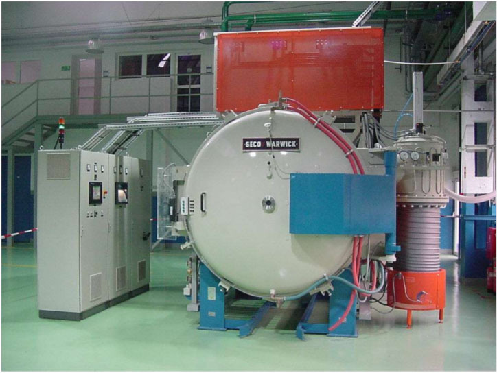
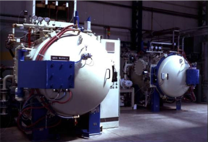
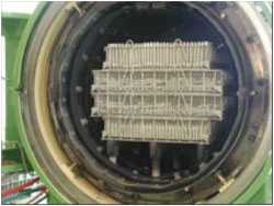
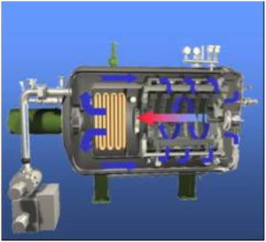
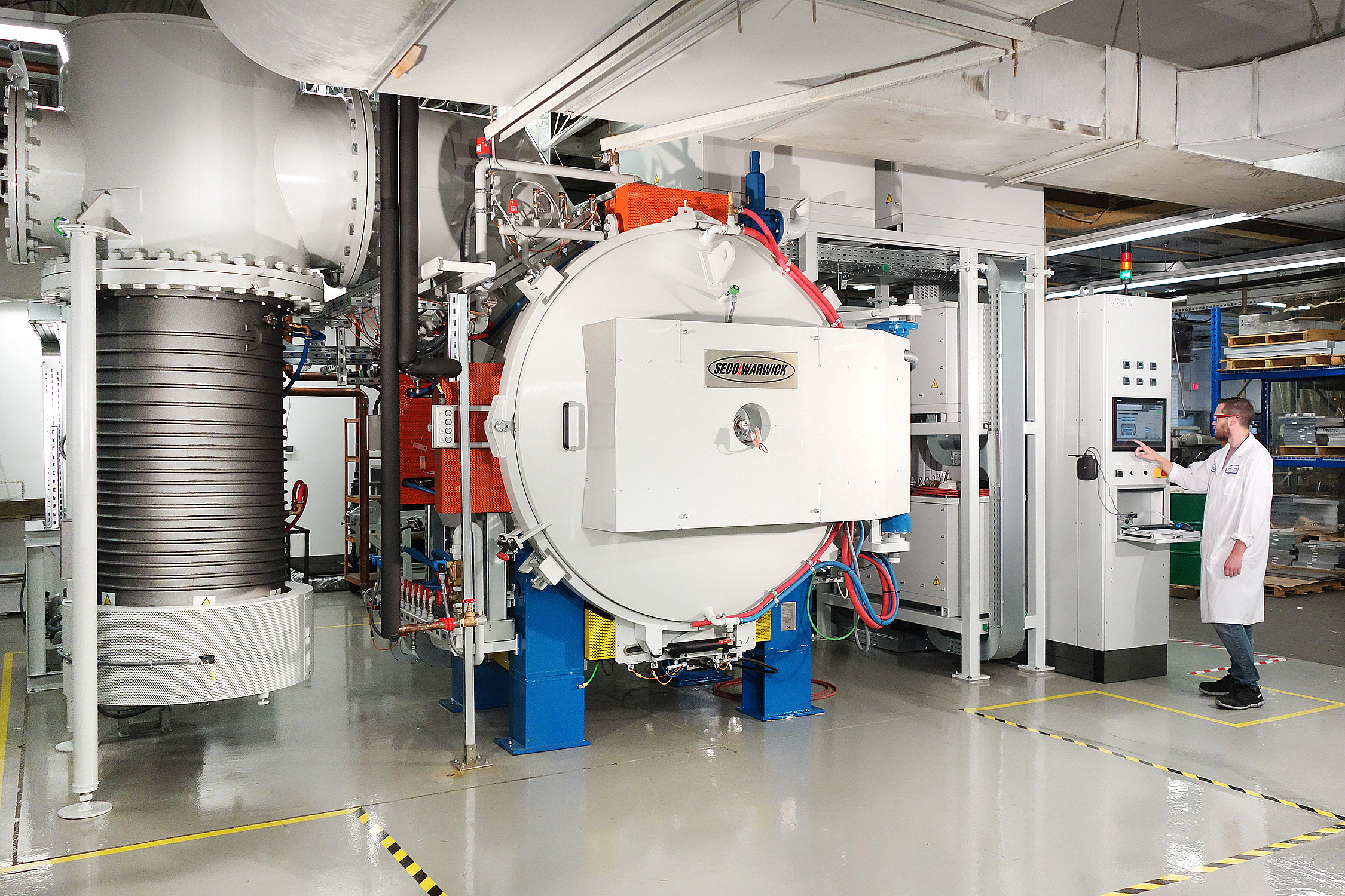
This vacuum brazing furnace is an advanced cold wall, front-loading vacuum furnace incorporating low or high pressure gas quenching. The furnace is of a compact design with an internal re-circulation blower and heat exchanger, requiring minimum floor space.
All-metal (or durable graphite) thermal insulation and heaters provide long, reliable service in this heavy-duty furnace designed for the industrial work place in aerospace industry. The pumping system, power supply and cooling systems are generously sized to enable a wide range of industrial heat treatment applications including brazing plus quench hardening and tempering, low pressure carburizing, annealing and solution heat treatment as well. The cooling gas re-circulation system includes a multi-nozzle gas feed arrangement to optimize the uniformity and rate of cooling of the load during quenching.
 SECO/WARWICK VP type Vacuum Furnace |
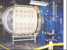
A horizontally oriented vacuum chamber is designed for front loading. It is fabricated from mild steel, sandblasted and epoxy-coated for vacuum service. A mild steel water jacket is provided for vacuum chamber cooling. The safety valve protects the vacuum chamber water jacket against excessive water pressure. To reduce corrosion of the furnace walls, deposition of impurities and build-up of scale, the water jacket should be supplied from a closed loop water system.
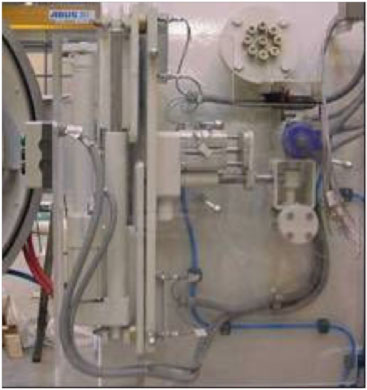 A hinged front door provides access for work loading, periodic cleanup and system maintenance. A lip seal located in a groove in the cover flange seals the flange-to-flange contact between the furnace chamber body and front cover, on closure of the vessel. Door clamp operated by linear motor allows positive pressure operations.
- Simple door clamping mechanism
- Prolonged service time of door sealing - no movement against mating flange
The chamber vessel wall contains the pump-out port and penetrations for power feedthroughs, system gauging, and instrumentation. Power feedthroughs are manufactured from copper and provide vacuum- and pressure-tight connections with heating element power terminals. A safety valve protects the vacuum chamber against an unexpected rise in backfill gas pressure. The chamber is supported from the operating floor by a structural steel weldment, which contains guides and stops to facilitate fork lift loading.
 SECO/WARWICK VP type Vacuum Furnace |
A vertically oriented vacuum chamber is designed for bottom loading. It is fabricated from stainless steel and polished from inside to improve vacuum performance.
A stainless steel water jacket is provided for vacuum chamber cooling. Water jacket is protected against rupture due to excessive water pressure by safety valve. To reduce corrosion of the furnace walls, deposition of impurities and build-up of scale, the water jacket should be supplied from a closed loop water system. Cooling water is drained from water jacket via manual ball valves installed in the bottom of the furnace vessel and cover.
The chamber cylinder wall contains the pump-out port, inlet and outlet ports for external gas cooling system and penetrations for power feedthroughs, system gauging, and instrumentation. Power feed-throughs are manufactured from copper and provide vacuum- and pressure-tight connections with heating element power terminals. Additional feed-throughs for power, system gauging and instrumentation are arranged in the bottom cover of the furnace.
The chamber is supported from the floor by a welded heavy support structure.
The bottom cover of the furnace with stainless steel water jacket provides full access for work loading, periodic cleanup and system maintenance. It is raised to its operating position with four ball screw lifters providing smooth and leveled travel. A lip seal located in a groove in the cover flange seals the flange-to-flange contact between the furnace chamber body and cover on closure of the vessel. A hydraulically operated cover clamp allows positive pressure operations up to 1,5 bar absolute.
To facilitate loading/unloading operations the bottom cover is moved aside from beneath of the furnace position with its own gear-motor drive. Roller-on-track driving system with appropriate limit switches control correct positions of the cover beneath the furnace for lifting operation and outside the furnace for loading/unloading operations. Conveniently located an operator’s push button station provides for operation of horizontal and vertical drives of the furnace cover. Power supply cables as well as cooling water supply and drain hoses connected to the furnace cover are suitably housed in flexible caterpillar.
A safety valve protects against an unexpected rise in backfill gas pressure.
To facilitate service and maintenance of the system, service platforms are installed around the furnace. The main platform is arranged on the main furnace flange level to enable service and maintenance of main furnace components.
All platforms and access ladders are guarded with appropriate railings.
 SECO/WARWICK VVP type Vacuum Furnace |
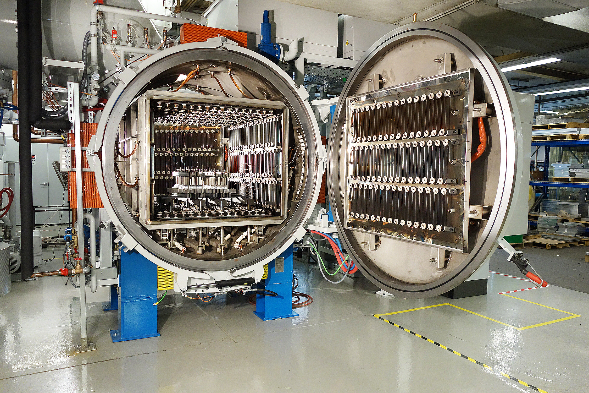
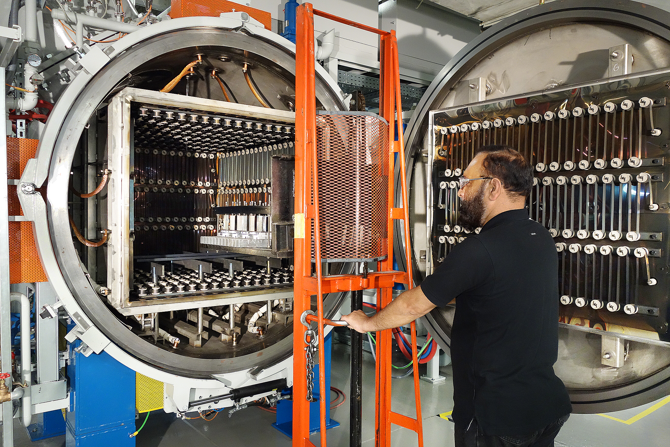
Graphite hot zone
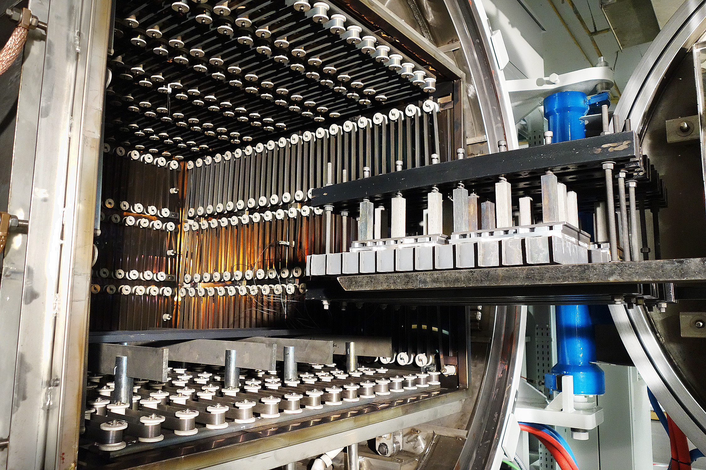
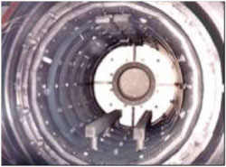 The graphite hot zone is designed for optimum temperature uniformity and rapid heating. Wide, low weight heating elements are assembled from curved graphite slats to form continuous 360° bands around the workload. The elements are arranged in few circuits, front-to-rear, for optimum temperature uniformity; individual slats are connected by graphite nuts and bolts to facilitate replacement in the event of damage. A minimum number of parts are used.
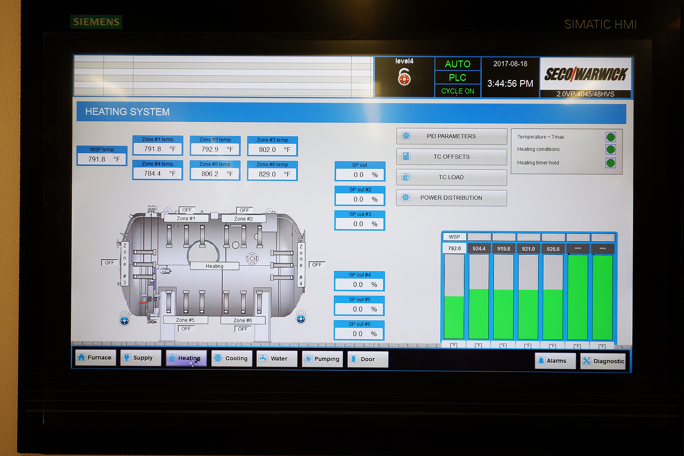
 Wide curved graphite heating elements improve temperature uniformity. Elements and power terminals are supported from water-cooled feedthroughs on the wall of the cylindrical heating chamber and are accessible from the hot face side of the thermal insulation assembly. The hot part of the power terminal is fabricated from graphite and is electrically isolated by a ceramic sleeve where it passes through the heat shield. Each graphite terminal is directly coupled to one of the copper power feedthroughs in the space between the hot zone and vacuum vessel.
The load is supported on molybdenum rod inserts by graphite hearth rails running from front to back of the hot zone. Graphite piers from the cold wall chamber support the hearth rails.
 Cylindrical heating chamber accommodates over-sized loads.
The rigid graphite insulation assembly comprises an optimum combination of graphitic materials; it is supported by a steel structure and prevents direct heat loss to the chamber wall. The insulation pack includes graphite boards backed by quality felt. The front insulation assembly is mounted on the vacuum chamber cover to provide direct and complete access to the hot zone for loading.
Optimum combination of graphite thermal insulation materials minimizes thermal losses to the furnace walls.
Modular construction permits convenient removal of the heating elements and insulation for periodic system maintenance.
Modular design of hot zone facilitates maintenance and repair operations.
All-Metal hot zone
The metal hot zone is designed for optimum temperature uniformity and rapid heating. Wide heating elements are fabricated from MoLa type molybdenum with improved resistance against mechanical shocks.
Segmented design provides for easy replacement of damaged part. Individual segments are assembled to form continuous 360° bands around the workload. Evenly distributed on the side of the hot zone heating elements provide optimum heat transfer to the workload. To improve stiffness of the elements they are corrugated along their length.
The elements and power terminals are supported from water-cooled feedthroughs on the wall of the cylindrical heating chamber and are accessible from the hot face side of the thermal insulation assembly. The hot part of the power terminal is fabricated from molybdenum and is electrically isolated by a ceramic sleeve where it passes through the heat shield (this ceramic is protected from the rigors of the cooling cycle) and is protected against metallization during brazing operation.
Each power terminal is directly coupled to one of the copper power feedthroughs in the space between the hot zone and vacuum vessel. The sidewall elements are arranged in few circuits, bottom-to-top, for optimum temperature uniformity; individual slats are connected by molybdenum nuts and bolts to facilitate replacement in the event of damage. A minimum number of parts are used.
The load is supported on easily removable molybdenum hearth rails located at the bottom of the uniform zone. The rails are supported on molybdenum piers from the furnace bottom cover.
The all-metal insulation assembly comprises an optimum combination of metal shields; it is supported by a stainless steel structure and prevents direct heat loss to the chamber wall. The thermal insulation assembly with sidewall heating elements are arranged on a modular stainless steel structure.
Modular construction permits convenient removal of the heating elements and insulation pack for periodic system maintenance. The bottom insulation assembly is mounted on the vacuum chamber cover to provide direct and complete access to the hot zone for loading.
Vacuum
The rough vacuum pumping system, including a mechanical vacuum booster backed by a rotary vane pump, is configured for automatically sequenced operation. A push-button starts the rotary vane pump to begin the vacuum chamber roughing cycle. When the chamber is preliminary evacuated the booster starts for high-speed evacuation. An oil diffusion pump with vacuum valve forms a separate pumping line for high vacuum operation. When the chamber vacuum level reaches 5 x 10⁻² mbar, the roughing valve, fore line valve, and high vacuum valve are automatically sequenced for high vacuum operation. A flexible bellows isolates the furnace from mechanical pump vibration.
The mechanical, booster and diffusion pumps are shipped with a full charge of pumping fluid.
|
A control manifold provides all necessary ports for vacuum and pressure gauging. A further valve port is provided for connection to the helium leak detector.
Operation of the pumping system is controlled by PLC and is fully automatic. An operator panel indicates the operating status of all system pumps and
valves.
Pressure
An inert atmosphere control system including an inlet valve, relief valve, and pressure gauges and switches is provided for vacuum chamber backfill.
Loads can be cooled in vacuum, still inert atmosphere, or re-circulated inert atmosphere depending upon process requirements. The chamber can also be backfilled to selected pressures, from slight above atmospheric to 1,5 bar abs. to optimize cooling rate. Optionally the chamber can be backfilled to high pressure up to 15 bar abs.
 The system includes an internal inert atmosphere re-circulation blower and a water-cooled finned-tube heat exchanger with the necessary pressure interlocks, switches, valves, starters, relays, etc. interconnected to make a complete operating system.
The cooling gas is injected uniformly onto the load through graphite nozzle arrays, which are deployed symmetrically in the hot zone cylinder and in the front insulation assembly. Special nozzle profile and high cooling gas velocity (up to 40 m/s) ensures excellent load space penetration and homogenous cooling. Hot gases escape the hot zone through a gas outlet bung in the rear wall.
A “soft-start” for the blower motor is also included. It reduces inrush currents, mechanical shocks and starting torque that are developed during full voltage starting.
Standard Technical Data
| Horizontal (VPT-) | Vertical (VVPT-EH-) | |||||||
|---|---|---|---|---|---|---|---|---|
| 4020/24 | 4025/24 | 4035/36 | 4050/48 | 4056/60 | 50/50 | 60/60 | ||
| Uniform Zone Size (WxHxL) | mm inch |
|||||||
| Hearth Capacity | kg | 200 | 400 | 600 | 1200 | 2500 | 1500 | 2000 |
| Operating Temperature Range | °C | 150-1350 | ||||||
| Convection Heating Range | °C | 150-850 | ||||||
| Temperature Uniformity | °C | ±5 | ||||||
| Heating Element Power | kW | 70 | 90 | 150 | 240 | 375 | 270 | 375 |
| Maximum Cooling Pressure | bar | 2-6-10-12-15 | ||||||
| Max. Convection Heating Pressure | bar | 3 | 2 | |||||
| Operating Vacuum Level | mbar | Range 10-2; 10-4 | ||||||
| Blower Motor Power - 10 bar - 6 bar |
kW | 75 | 90 | 135 | 240 | 240 | 135 | 240 |
| Cooling Gas (N2) Consumption (1 bar pressure) |
Nm3 | 1,5 | 2,4 | 5,5 | 7,5 | 10,0 | 7,5 | 15 |
| Cooling Water Consumption | ||||||||
| -During Heating Cycle | m3/h | 2 | 4 | 6 | 10 | 16 | 10 | 16 |
| -During Quench Cycle - 10 bar - 6 bar |
m3/h | 15 | 20 | 40 | 75 | 90 | 40 | 60 |
| Furnace Size (WxHxL) | m | 2.5x2.5x4 | 2.6x3x4 | 3.2x3.6x5.5 | 3.5x4x7 | 4.6x4x8 | 6x7.5x7 | 7x8x8 |
Controls
Temperature Instrumentation features are as follows:
- PLC based digital temperature controller/programmer including a PID current proportioning temperature controller and calibrated and compensated thermocouple inputs.
- Indicating over-temperature protector calibrated and compensated thermocouple input with thermocouple break protection.
- Thermocouple assembly, including insulated thermocouple, vacuum feedthroughs, and polarized connector.
- Multiple thermocouple feedthroughs for connection to twelve (12) type N thermocouples.
Control System
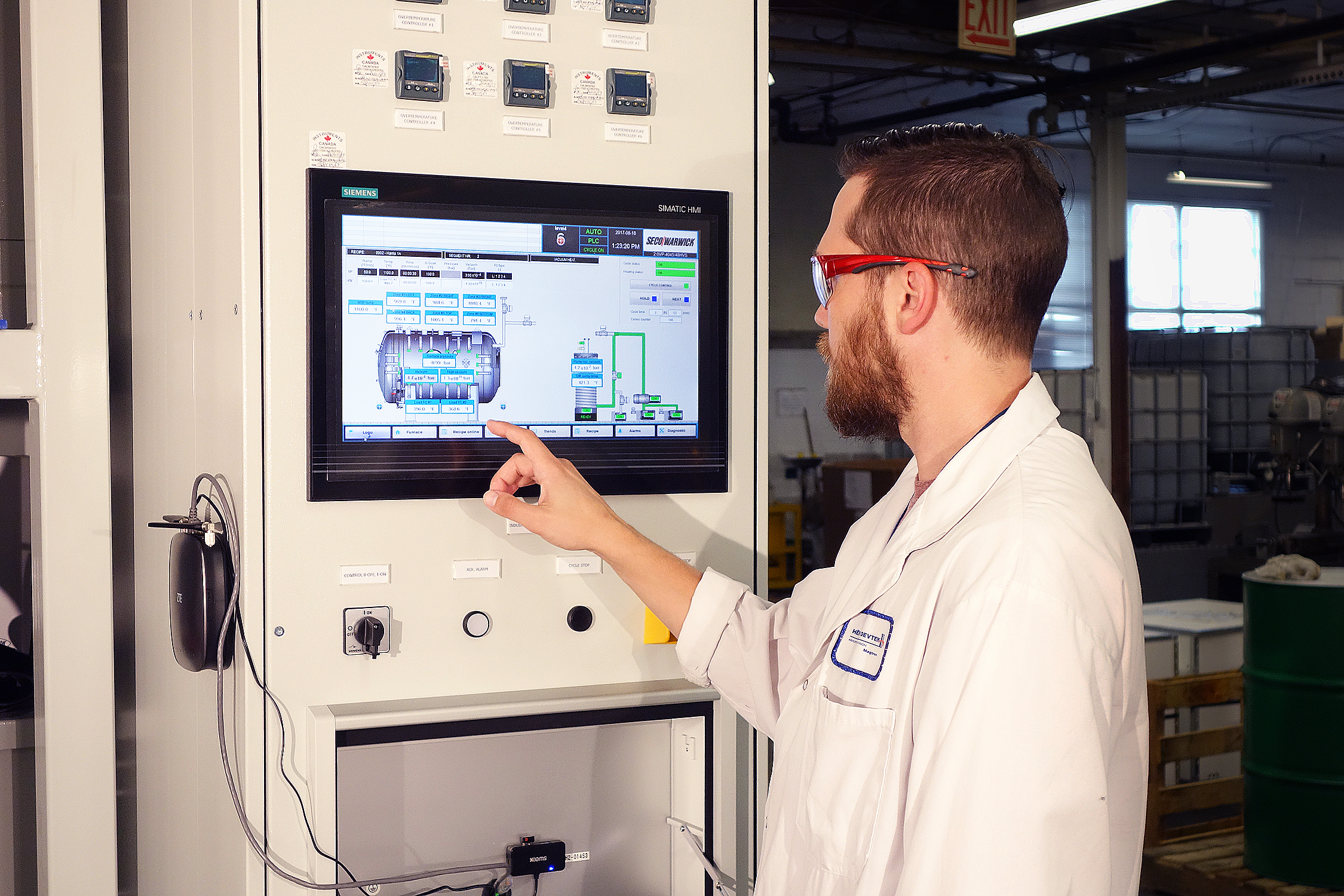
The vacuum furnace control system is composed of the control cabinet complete with measuring/control equipment provided with the human-machine interface (HMI) for the operator and with the sensors and actuating members installed on the furnace, complete with the interconnecting installation.
The system is designed in conformity with the valid directives, standards and regulation of the CE or American market and covers the materials and component relevant for the thermal treatment equipment. The design ensures the furnace functionality and reliability, and absolutely warrants safety of the operating staff when operated correctly.
The system documentation has been prepared in the WSCAD standard and may be delivered in the paper form or on any electronic medium (in the .dxf format). The documentation has been developed in the circuit-based system where any component, connection terminal and wire possess individual identifications (markings) and references. This makes the documentation clear and comprehensible for a normal electrician, even without a specialized training. Due to its logical structure and easy identification of components, the circuit-based documentation system is recognized with approbation by wide circles of the run maintenance services.
The control system is manufactured by a specialized staff with many years of experience and, undergoes full (100%) tests during the stage of testing. The tests and checks refer, separately, to any components, subassembly, assembly, mechanism and system, up to the complete furnace, and cover the safety as well as the functionality.
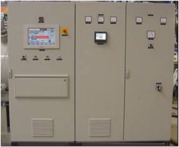 The control cabinet is built on the basis of electrical enclosures supplied by the Rittal Company, and have a IP54 environmental rating and meets electromagnetic compatibility requirements. It constitutes a single unit (stand alone or built into the furnace) but, functionally, it is divided into several sections. The main isolator is located in the power supply section, is equipped with the appropriate short-circuit and overload protection and electric bus bar distribution system.
The power distribution section covers the power safety system, contractors, automatic control devices and connection strips for the power outputs, e.g. pump motors, heating components, gas blower motor, etc. In the control section is located the power supply units, electrical/electronic measuring & control components, electrical protections and connection strips for the control circuits, the programmable logical controller (PLC) and the operator’s interface.
The equipment located inside the cabinet is driven by the either 230 VAC or 115 VAC, or 24 VDC. The cabinet is provided with the cooling fans and internal illumination. The user has only to connect the main electric power supply of the TN type, directly to the main isolator terminals;
The connections cover the line wires L1, L2, L3 and the protective conductor PE. The neutral conductor N is not used and it is not needed to be connected. The control cabinet is provided with a separated circuit for the service outlet and illumination, this is fed via connections from the mains input side of the main isolator; therefore, no additional supply except the main supply is needed. The main isolator mechanism is mechanically interlocked to protect against opening the control cabinet door when the power supply is on.
From the operator’s point of view, the following components are installed on the control cabinet:
The main isolator ON/OFF switch, (excluding the interior lights and service socket)
Heating component current ammeters,
Blower motor current ammeters,
Protective temperature controller,
Control voltage disconnect,
Control push-buttons (start, stop, alarm acknowledgement),
Emergency stop
Operator’s interface.
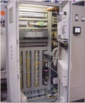 The programmable logical controller (PLC) monitors the furnace operation, where to all input (analogue and digital) signals from the equipment and sensors are connected and which operates the actuating members of the furnace with use of digital and analogue signals.
In accordance with the above description, the PLC controller monitors and controls the analogue process characteristics of the furnace, such as the temperature value in accordance with the PID control algorithm, the vacuum value and the pressure value. Absolutely all actuating systems are provided with individual protection and acknowledging components or components analyzing operation. This results in the systems being completely diagnosable and location of any possible failures may be done accurately, effectively and quickly.
The furnace operating sequence is written in a form of a program in the Central Processing Unit (CPU) of the controller and is stored in the nonvolatile memory.
In the circuits concerning safety, hardwired interlocks ensure safety even in the event of an emergency fault condition in control the system is provided.
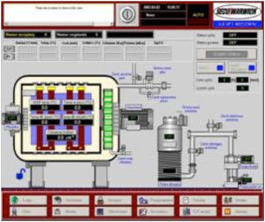 The control commands and the furnace operating programs may be loaded into the logical controller with use of the graphical operator’s interface, developed on the basis of the Industrial Personal Computer (IPC) is provided with a color touch screen (waterproof and dust proof). The communications between the logical controller and the operator’s interface are possible via the internal network of the “Ethernet” type, equipped, as per standard, with the equipment enabling connection to an external communication network (Hub, Router and modem).
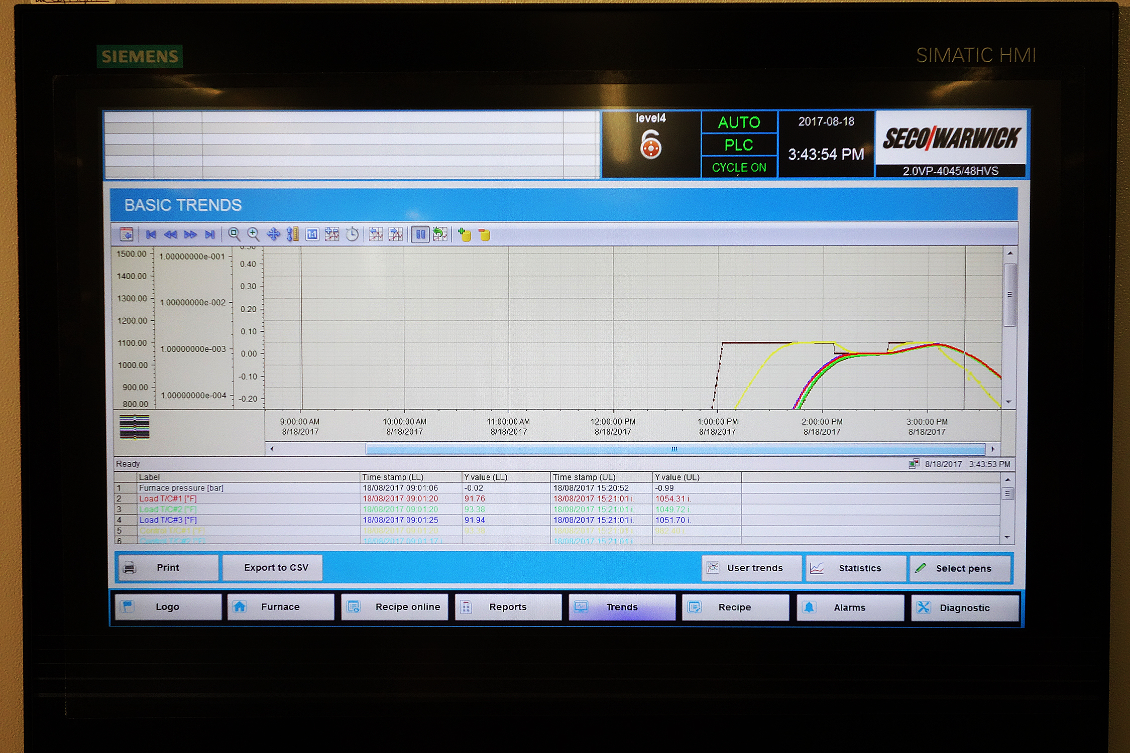
The operator’s interface software is consists of the operator’s program developed on the basis of In-Touch (e.g. the program named SecoVaC). The program is very easy and user-friendly, and enables operation in an intuitive way. Individual functions and operator’s actions may be obtained with use of dedicated screens, e.g. the main screen, recipe edition screen, characteristic recording screen, alarm screen, technical screen, inspection and maintenance screen, service screen, etc.
The program is provided with, among other things, the following functions and features:
- Graphical and dynamical furnace imaging,
- Component condition and state visualization,
- Display of technical characteristics,
- Recipe edition (furnace operating programmes),
- Operation monitoring (start, stop, stoppage, skipping, programmable start),
- Current edition of the recipe under execution (on-line operation modification),
- Data logging,
- Alarming,
- Maintenance service program,
- Furnace parameterization,
- Operation in AUTO or MANUAL modes
The operator’s program advantages presented, in conjunction with the industrial computer of the class IPC, provided with a touch screen, result in a tool, which is easy in operation and reliable, intended for communications between the furnace and the operator.
Sensors and Actuators
The sensors and actuators are installed on the furnace to allow correct operation and avoiding any possibility of their damages in normal use. They are protected against influence of the environmental conditions and driven with the safe direct current voltage 24 VDC. The electrical wiring on the furnace is installed in ducts and pipes that make it very durable and resistant to mechanical damage; the installation is distributed from a single point – the connection cabinet. The delivery scope covers the complete set of the conductors connecting the furnace to the control cabinet within the specified dimensions.
Unique Control System Advantages
- One three-phase power supply connected at a single point,
- The neutral conductor N not used,
- Safe control voltage on the furnace, 24 VDC,
- Full condition and state diagnostics,
- Electrical protection on each actuating component, univocal disturbance identification,
- Internal communication network of the Ethernet type,
- Built-in equipment for interconnections with an external communication network and telephone line,
- The operator’s interface in the form of an IPC computer, provided with a color, water- and dust-proof touch screen,
- Operator-friendly software (SECO/VACUUM (SECO/WARWICK Vacuum Control)) based on In-Touch (Wonderware),
- Unlimited number of furnace operating programs (recipes) stored on HDD in IPC,
- Up to 25 various stages (segments) in a program,
- Programmable furnace operating cycle start time,
- As per standard, two load thermocouples,
- Advanced temperature control functions:
- Batch-type thermocouple monitoring,
- Guaranteed soak time function
- Automatic temperature control in accordance with a selected load temperature value,
- Programmable vacuum interlocks for heating,
- Possible adaptation of the furnace to the local conditions – through parameterization
The control system presented above is not only easy in use, reliable, open and flexible, but it enables also real-time data logging, data exchange and processing, and may be customized in accordance with the local requirements and the Customer’s needs.
Protections and Safety Interlocks
- The vacuum chamber is manufactured according to applicable norms and standards acceptable in the end- user country (UDT, CE, TUV, ASME).
- A relief valve protects the vacuum chamber from excessive gas pressure increases.
- A relief valve protects the vacuum chamber water jacket from excessive water pressure increases.
- The furnace door can be safely opened only after the furnace and ambient pressures are equalized.
- Electrical actuators have built in short circuit protection, and all the motors have protection against overload.
- In the event of power supply failure all valves go to a failsafe condition, and the furnace safely waits for the power to be restored. When the power supply is restored, the furnace can continue the interrupted cycle.
- In the event of a compressed air pressure drop, the cycle is immediately stopped and all valves go to a failsafe condition. Once the pressure is restored the furnace can continue the interrupted cycle.
- An emergency stop button is provided which, when actuated by the operator cuts off the power supply to all actuators and stops the cycle. Once the situation is cleared the furnace can continue the interrupted cycle.
- In the event of cooling water supply failure the heating system and cooling blower are shutdown.
- Temperature sensors installed in the water jackets of the furnace door and the furnace body shut down the heating system when water temperature rises above a pre-set over-temperature value.
- A failure in water flow through the furnace heat exchanger cooling circuit shuts down the blower motor.
- The heat treatment cycle is fully automatic and does not require any operator intervention. The cycle is completed, once the charge is cooled down and ready for removal from the furnace. The furnace door can be opened safely once the load temperature is adequately low and pressures inside the furnace are equalized with ambient conditions.
- In order to start the heat treatment cycle the operator has to select the required recipe from within stored recipe cycle programs.
- A negative furnace leak test prevents the work process cycle starting or allowing its continuation.
- When the pressure inside the vacuum vessel exceeds a pre-set value, the heating system is shutdown to protect the heating chamber from oxidation.
- The furnace is equipped with an independent temperature control system with a separate thermocouple and temperature controller. When the temperature rises over the pre-set value the over temperature controller will immediately shutdown the furnace heating system.
- All abnormal situations activate the audible and visible alarms and the fault information is displayed on the operator panel.
- All vital furnace parameters, alarms and events are recorded in real time on the furnace industrial computer hard drive disc.
Vacuum Furnace Processes
Fine Carb®: Vacuum Carburizing High Pressure Gas Quench High Vacuum Furnaces PreNit: High Speed Vacuum Carburizing Vacuum Brazing: Advanced Front Loading Gas Nitriding with ZeroFLow® FURNACE/PLUS Vacuum Circuit Breaker Brazing
Specifications Subject to Change without Notice
 Request Quote/Info
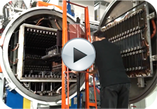 Video: Heroux Devtek Vacuum Aluminum Brazing
